M5Stack® Wireless COMMU Module Extend RS485/TTL CAN/I2C Port with MCP2515 TJA1051 SP3485 Development Board for Arduino EP32 Kit

Arduino
sku: 1537070
ACCORDING TO OUR RECORDS THIS PRODUCT IS NOT AVAILABLE NOW
$14.99
Shipping from: China
Description
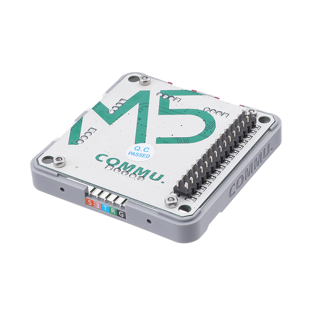
Description: COMMU is a Muti-Communication-Interface-Converter. Integrated with 2IIC, 1TTL, 1CAN, 1RS485. Apparently COMMU has packed with most of series communications. Default connection: TTL - UART0, RS485 - UART2. Since ESP32 pin map is allowed for re-assign, you can re-assign or re-mapping the TTL or RS485 interface to other pins. Be care about TTL Interface. It is a UART Interface actually by default. But you can switch it to connect with UART2 after changed those jumpers(J6, J7, J9, J10). Product Features: 2x I2C Interface 1x CAN Interface 1x RS485 Interface 1x TTL Interface CAN controller: MCP2515-1/SO RS485 Transceiver: SP3485EN-L/TR Product Size: 54.2mm x 54.2mm x 12.8mm Product weight: 13.5g Package Included: 1x M5Stack COMMU Module PinMap: CAN ESP32 Chip CAN_CS GPIO12 CAN_INT GPIO15 CAN_SCK GPIO18 CAN_MISO GPIO19 CAN_MOSI GPIO23 I2C Interface ESP32 Chip IIC_SDA GPIO21 IIC_SCL GPIO22 Related Link: Offical Video Forum Datasheet SP3485 MCP2515 EasyLoader click to download EasyLoader 1.EasyLoader is a simple and fast program burner, and each product page has a product-related case program for EasyLoader. 2.After downloading the software, double-click to run the application, connect the M5 device to the computer via the data cable, select the port parameters, and click "Burn" to start burning. 3.The CP210X (USB driver) needs to be installed before the EasyLoader is burned. Click here to view the driver installation tutorial Example: for Arduino IDE CAN communication These are two COMMU examples for CAN communication, tansmitter and receiver. Press Button A to sent the message, and display the received message on the screen. Step 1: Copy MCP_CAN_lib file to C:UsersDocumentsArduinolibraries, Step 2: Open project file commu_can_transmitter.ino, and commu_can_receiver.ino Step 3: Compile and upload the two project to two M5Cores separatly. The below code is incomplete(just for usage). If you want the complete code, please click here. /* commu_can_transmitter.ino */ #include #include #include "m5_logo.h" #define CAN0_INT 15 // Set INT to pin 2 MCP_CAN CAN0(12); // Set CS to pin 10 // declaration byte data[8] = {0x00, 0x01, 0x02, 0x03, 0x04, 0x05, 0x06, 0x07}; // initialization M5.begin(); CAN0.begin(MCP_ANY, CAN_1000KBPS, MCP_8MHZ); /* Change to normal mode to allow messages tobe transmitted */ CAN0.setMode(MCP_NORMAL); // send data CAN0.sendMsgBuf(0x100, 0, 8, data);Copy to clipboardErrorCopied /* commu_can_receiver.ino */ #include #include #include "m5_logo.h" #define CAN0_INT 15 // Set INT to pin 2 MCP_CAN CAN0(12); // Set CS to pin 10 // declaration byte data[8] = {0x00, 0x01, 0x02, 0x03, 0x04, 0x05, 0x06, 0x07}; // initialization M5.begin(); /* Initialize MCP2515 running at 16MHz with a baudrate of 500kb/s */ /* and the masks and filters disabled. */ CAN0.begin(MCP_ANY, CAN_1000KBPS, MCP_8MHZ); /* Set operation mode to normal so theMCP2515 sends acks to received data. */ CAN0.setMode(MCP_NORMAL); pinMode(CAN0_INT, INPUT);// Configuring pin for /INT input // read data CAN0.readMsgBuf(&rxId;, &len;, rxBuf);Copy to clipboardErrorCopied RS485 communication This is a COMMU example for RS485 communication. Burn example to two M5Cores. Then after pressed Button A, this two cores will send message to each other and receive data.
Price history chart & currency exchange rate
Customers also viewed


$12.14
1 пара, датчик скорости заднего левого и правого колес 118877100A для Tesla Model 3 2017, модель Y 2019
aliexpress.ru

$11.02
Щетка Для Чистки унитаза, силиконовая щетка для унитаза с многоразовым дозатором ручки, щетка для чистки туалета
aliexpress.ru
$4.47
Handmade Fake Nails Blush Manicure Light Luxury Girly Dreamy Pink Ballet Personalised Acrylic Full Cover Nail Tips for Girls
aliexpress.ru
$19.88
Original Internal Hard Drive Solid State Disk NGFF M.2 SSD 1TB 2TB PCI-E High Speed Interface Hard Disk for Desktop/Notebook PS5
aliexpress.ru
$13.12
Детские Блестящие Блестки для девочек, сетка без рукавов, с вырезами на спине, Lyrical танцевальная модель, танцевальная одежда балерины
aliexpress.ru
$9.12
32 Pcs Toss Ring Outdoor Playsets Toddlers Sports Targets Throwing Plastic Games Props
aliexpress.ru


$39.90
Luxury Ladies Watch Strap For Apple Watch Series 1 2 3 Wrist Band Hand Made By Crystal Bracelet For Apple Watch Series iWatch
aliexpress.com

$15.00
M M's Chocolate Candy Shopping Bag Aesthetic Cloth Outdoor Handbag Female Fashion Bags
aliexpress.com
$18.97
Women Ladies Satin Silk Night Dress Deep V Nightdress Summer Sleeveless Dress Sexy Lingerie Nightgown Sleepwear Wedding Bride
aliexpress.com

$42.29
Benchmade 537 Bugout AXIS Folding Knife 3.4" CPM-3v Blade Titanium Alloy Handles Pocket Knives Rescue Utility EDC 537GY BM537 535 9400 940 15080 Tools
dhgate.com
$4.95
4 шт./кор. многоразовые силиконовые удаляющий шрамы патч удалить травмы ожога лист восстановления кожи лечение шрамов терапия патч Здравоох...
aliexpress.com


$64.60
Low Pressure Fuel Pump & Stainless Bracket 8M0047624 For Mercury Mariner 8558432
aliexpress.com Amelie Galanti 3771, Черный")

$23.52
Note Paper Art Diy 3D Memo Notes Pads Convenience Stickers Papers Card Craft Creative Post Notes Paper Art Crafts
aliexpress.com
$120.64
SZSGCN428 Men 's High White Shoes 2019 New Korean Hip-Hop Casual Shoes Men White/Black Hot Fashion Lace Large Size Men Shoes
aliexpress.com
$3.68
Travel Bathroom Silicone Portable Camping Folding Wash Basin Collapsible Bucket/ Dish Tub
aliexpress.com")
$4.33
SULADA Plating Edge TPU + Leather Magnetic Protective Case for iPhone XR (Brown)
sunsky-online.com
$5.61
Mma Rashguard for Men Jiu Jitsu Compression Shirt Fitness Tops Short Sleeve Kickboxing Gym Fightwear Boxeo Muay Thai T-Shirts
aliexpress.com

