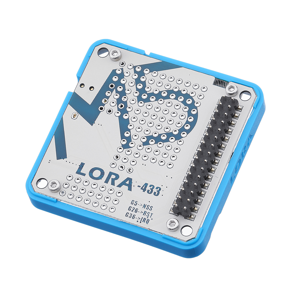
M5Stack® 433MHz Wireless LoRa Module for ESP32 DIY Development Kit Built-in Antenna IOT Development Board

Eachine1
sku: 1537061
ACCORDING TO OUR RECORDS THIS PRODUCT IS NOT AVAILABLE NOW
$9.95
Shipping from: China
Description
Description: LoRa integrated LoRa Module Ra-02, designed and produced by Ai-Thinker. On the board has some extra space left over, so we give you a prototyping area, it's great for adding on your customized circuit working with the LoRa Module. LoRa enables long-range transmissions (more than 10 km in rural areas) with low power consumption,The technology is presented in two parts: LoRa, the physical layer and LoRaWAN (Long Range Wide Area Network) the upper layers. LoRa and LoRaWAN permit long-range connectivity for Internet of Things (IoT) devices in different types of industries. Product Features: Lora Module: Ra-02 (by Ai-Thinker) Series Communication Protocol: SPI Universal Perboard Working Frequency: 433 MHz Supports FSK, GFSK, MSK, GMSK, LoRa and OOK modulation modes Receive sensitivity: lowest to -141 dBm Programmable bit rate up to 300Kbps Build-in PCB Antenna External Antenna port Program platform: Arduino, Mrcropython, UIFlow(Blockly) Product Size: 54.2mm x 54.2mm x 12.8mm Product weight: 14.5g Package Include: 1x M5Stack LoRa Module Applications: Automatic meter reading Home building automation Remote irrigation system Related Link: Offical Video Forum LoRa Info (LoRa) LoRaWAN Regional Parameters EasyLoader click to download EasyLoader 1.EasyLoader is a simple and fast program burner, and each product page has a product-related case program for EasyLoader. 2.After downloading the software, double-click to run the application, connect the M5 device to the computer via the data cable, select the port parameters, and click "Burn" to start burning. 3.The CP210X (USB driver) needs to be installed before the EasyLoader is burned. Click here to view the driver installation tutorial Example: for Arduino IDE These are the point-to-point communication examples between two LORA modules. The LoRa nodes send and receive messages. Blue string indicates sending succeed. Yellow string display the received messages. Red string indicates initialization failed. To get complete code, please click here #include #include //declaration String outgoing; // outgoing message byte msgCount = 0; // count of outgoing messages byte localAddress = 0xBB; // address of this device byte destination = 0xFF; // destination to send to //initialization M5.begin(); LoRa.setPins(); // set CS, reset, IRQ pin LoRa.begin(433E6); // initialize ratio at 915 MHz //send message void sendMessage(String outgoing) { LoRa.beginPacket(); // start packet LoRa.write(destination); // add destination address LoRa.write(localAddress); // add sender address LoRa.write(msgCount); // add message ID LoRa.write(outgoing.length()); // add payload length LoRa.print(outgoing); // add payload LoRa.endPacket(); // finish packet and send it msgCount++; // increment message ID } //receive message void onReceive(int packetSize) { if (packetSize == 0) return; // if there's no packet, return int recipient = LoRa.read(); // recipient address byte sender = LoRa.read(); // sender address byte incomingMsgId = LoRa.read(); // incoming msg ID byte incomingLength = LoRa.read(); // incoming msg length String incoming = ""; while (LoRa.available()) { incoming += (char)LoRa.read(); } } onReceive(LoRa.parsePacket());Copy to clipboardErrorCopied Schematic:
Price history chart & currency exchange rate
Customers also viewed

$19.06
Апельсины на черном платье без рукавов Бандажное платье женская одежда Вечерние платья милое платье
aliexpress.ru

$110.68
canvas shoes slerepublic tan jianci ethnic cloth low-top platform women's all-match shoes size 35-40
fordeal.com


$89.32
men's training coat us military uniform winter plus size camouflage jacket shark soft shell tactical 211214, Black;brown
dhgate.com
$54.96
autumn new full loose plus size chiffon floral print dress for women 210421, Black;gray
dhgate.com
$68.33
2022 Men' Hoodies & Sweatshirts sweater suit for men and women couples autumn European and American version casual Joker loose round neck fashion clothes 520, White
dhgate.com
$91.58
real pos black 3 meters 2 layers bling sequins long wedding veil with comb new bridal veil bridal accessories5706655
dhgate.com


$12.77
plain neon yellow women sun ladies golf tennis running visor bright color pink orange adjustable, Blue;gray
dhgate.com
$14.39
RGB Gaming Mouse Pad Large Size Colorful Luminous for PC Computer Desktop Jurassia Park LED Light Desk Mat Gaming Keyboard pad
aliexpress.com
$23.35
zip-up Harajuku Oversized Hoodies For Women clothes Hooded long Sleeve Jumper Hooded Regular Coat Casual korean style Sweatshirt
aliexpress.com
$4.74
Plant Covers Frost Protection Drawstring With Zipper Plant Fruit Tree Garden Fabric Potted Freezing Protected Bug Insect Barrier
aliexpress.com
$3.57
Автомобильный Fm-передатчик, Bluetooth-совместимый, 5,0, а, Быстрая Двойная автомобильная зарядка, светодиодное зарядное устройство, Usb автомобиль...
aliexpress.com
$2.60
Ролевые новые металлические штампы трафареты для «сделай сам» Скрапбукинг Декоративные ремесла тиснение бумажные карты вырез 2
aliexpress.com
$116.83
00010 Lastest Men Football Jerseys Hot Sale Outdoor Apparel Football Wear High Quality
dhgate.com
$7.73
MVUPP christmas snowflake family long t shirt for mother daughter father son matching clothes fashion outfits family patchwork
aliexpress.com")
$7.19
Aabhaas Wall Poster For Room Cute Adorable Baby Child's Love New Born Infant Kids Toddlers Smiling Paper Print(12 inch X 18 inch, Rolled)
flipkart.com
")
")
