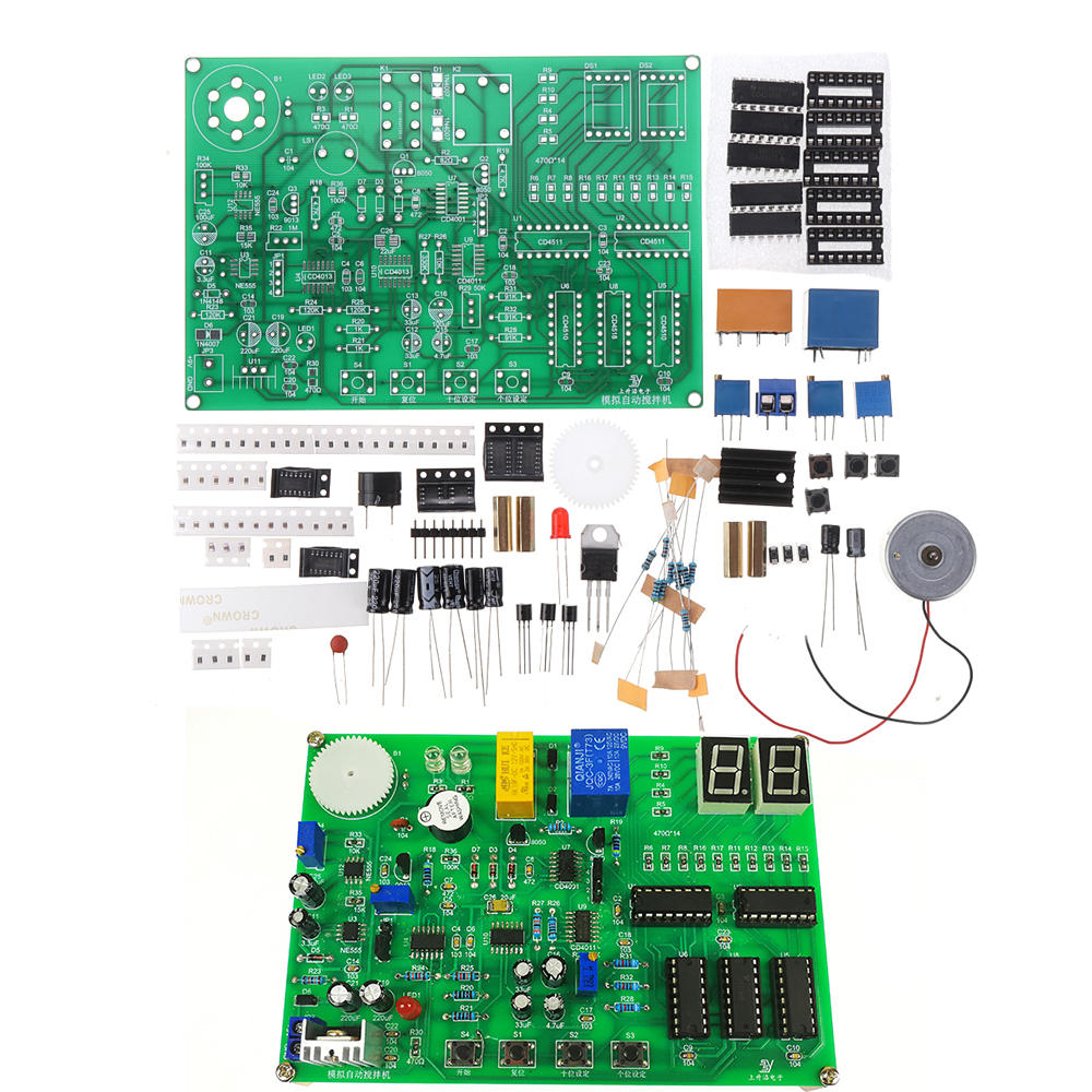
DIY Simulation Automatic Mixer Kit Soldering Practice Board Electronic Assembly Troubleshooter Competition Kit

Eachine1
sku: 1613961
type: Electronic Components & DIY Kits
ACCORDING TO OUR RECORDS THIS PRODUCT IS NOT AVAILABLE NOW
$26.99
Shipping from: China
Description
Circuit function description 1 The second signal generation circuit debugging U3 consists of first inserting the short circuit cap to the 1 and 2 positions of JP1 connecting the high level of VCC to the four pins of U3 then adjusting the precision adjustable resistor R22 and using an oscilloscope Observe the square wave output from pin 3 of U3 and make its frequency 1HZ After debugging please pull out the short circuit cap and insert it into 3 and 4 of JP1 2 Debug the stirring control circuit composed of U7 U9 U4 first insert another short circuit cap to the 1 and 2 positions of JP2 and connect VCC high level to the 3 pin of U9A and then adjust the precision adjustable Resistor R29 loops the 11 pin output of U9D for a period of 3 seconds high and 3 seconds low That is to make the stirring motor work in a cycle of forward 3 secondsdash stop 3 secondsdash reverse 3 secondsdash stop 3 secondsdash forward 3 seconds At this time the cycle of LED2 and LED3 is LED2 on LED3 ondash dash LED2 off LED3 ondash dash LED2 on LED3 offdash dash LED2 off LED3 offdash dash LED2 on LED3 is on After the stirring circuit is debugged normally please pull out the short circuit cap and insert it into 3 and 4 of JP2 3 After the prompt tone circuit is debugged after adjusting the second signal generation circuit and the stirring control circuit use the keys S2 ten digits to S3 one digit to set the appropriate stirring time and then press
Price history chart & currency exchange rate


