12 Channel RGB DMX 512 LED Controller Decoder Dimmer Driver For LED Strip Module Light DC5V-24V

Eachine1
sku: 1143727
ACCORDING TO OUR RECORDS THIS PRODUCT IS NOT AVAILABLE NOW
$52.27
Shipping from: China
Description
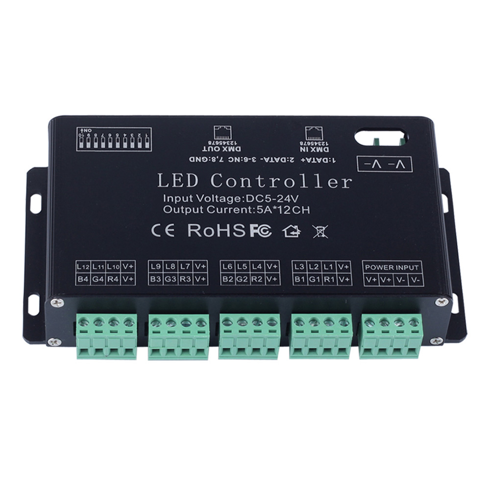
Introduction: Welcome to use the 12CH constant decoder, which take advantage of advanced microelectronic control technology. This technology changes the international fashion DMX512/1990 standard digital control signals into analog control signals. There are 1 ~ 12 output channels; each channel can achieve 256 control levels. This constant decoder is used when DMX512 control equipment control general LED lighting. Specifications: Input Power:DC5V-DC24V Maximum Load Current: 5A/CH12 Maximum Power Load: 300W(5V)720W (12V);1440W (24V) Output Gray Level: 256 Input Signal DMX512/1990 Output Signal:12 Channels Constant PWM Output DMX: 12 Channels DMX512 Socket Standard RJ45; Size:L155*W88*H32MM Basic functions: *There are 12 output channels, can connect with single or RGB lamps *0-100% dimming output, each channel 256 gray levels *International standard DMX512 input protocol, address code set by DIP switches *Wide voltage DC input DC5V ~ DC24V *Each occupied by 12 DMX address Package Included: 1 X LED DMX512 Controller 1 X English User Manual Connection Diagram: The signal line connection diagram: 1 : DATA+ 2: DATA- 3-6: Empty 7-8:GND The first DMX address setting: The decoder set the address bit by coding switch, of which 1-9 is for setting the start address of the Binary numeric code switch of DMX512, the first one is the lowest position, the ninth one is the highest Bit of address code can be set to 512. DMX512 start address code is the sum of switches 1-9, at the same time turn downside of the code switch (ON set to "1") then the value of the bit can be gotten; coding switch up (set to "0") the value of the bit is 0. Example 1: As the following Schematic 1, DMX512 start address is set to 38,encoding the No. 6,3,2 position on switch dial to "1" others set to "0",then the sum of the switch 1-9 code value is 32 + 4 + 2,that is the DMX512 start address 38 Schematic 1 Example 2: As the schematic 2, DMX512 start address is set to 388, encoding the no. 2,3,6,8 switch dial to "1" others set to "0",then the sum of the switch 1-8 code value is 4 + 128 + 256 = 388,that is the DMX512 start address 388. Schematic 2 Operation instruction for the automatic effect Note: It will be Automatic operation mode when the No. 10 switch is turned down. Effect choice (button switch No.1 to No.4): 1, Push No.1: Automatic cycling. 2, Push No. 2: Seven-color gradual cycle changing. 3. Push No.1 &2: RGB Fade in and out 4. Push No.3: Severn color jumping 5. Push No.1 & 3: RGB jumping. 6. Push No.2 & 3: Single color fade 7. Push No. 1 & 2 & 3:Single color left scan 8. Push No.4: Single color right scan 9. Push No.1 & 4: Single color left pile up 10: Push No.2 & 4: Single color right pile up 11. Push No.1 & 2 & 3: Single color left and right scan 12. Push No.3 & 4: Single color left and right pile up 13. Push No.1 & 3 & 4: single color red 14. Push No.2 & 3 & single color green 15. Push No.1 & 2 & 3 & 4: single color blue Speed Choices (Button Switch No.5 to No. 8) 1.Push No.5: 0.5 second. 2. Push No.6: 1 second. 3. Push No.7: 1.5 second. 4. Push No.8: 2 second. Schematic for System Connection: Plan one:DMX512 Console+12CH DMX decoder Plan two:PC DMX512 Console+USD DMX controller+12CH DMX decoder Installation Notes: 1 This kind of controller works only under DC5V-24V, which is provided by the matched controllable main power, or else the controller will be damaged. 2 The UTP wire is connected hand in hand to make the cable, when two or more controller connected. 3 The power supply should be off when connecting the electric wires, and it can be turned on till making sure the wires are connected correctly and the indicator of main power in red is lighting. 4 Controller should work under the environment of adequately ventilated, dry, not corroded, no flammable gas and rust. 5 Please check the wires connection regularly so that the wires of aged, rust-eaten, and damaged insulation spacer can be replaced timely Simple troubleshooting and maintenance: FAQ: 1. Input voltage is normal? Ensure input voltage DC 5-24V, cathode connected DC + negative pole DC-. When the normal power supply, the controller red indicator light on. 2. The DMX decoder controller needs DMX master control. The controller is a DMX decoder. You must use DMX master control it. DMX master such as: USB DMX master, DMX console. 3. The decoder is not controlled? (1) Ensure that the decoder signal line connected to right. Negative signal decoder corresponding master negative, Positive signal decoder corresponding to the master positive, GND decoder corresponding to the master GND. (2) Ensure that the decoder is DMX mode, DIP switch tenth position must be zero. 4. How adjustment whether the decoder received DMX signal? The decoder of the green indicator light flashes slowly or does not flash when no signal is received, indicating that the received signal when the green indicator light quick flashes.
Price history chart & currency exchange rate
Customers also viewed


$123.66
men's jackets mens japanese embroidered sukajan souvenir flight jacket bomber birds coat chic men, Black;brown
dhgate.com
$11.66
jewelry s925sterling silver needle earrings for women velour circle round fashion of shipping
dhgate.com
$37.85
2021 customize 33 viktor arvidsson nashville predators jerseys golden edition camo veterans day fights cancer custom stitched hockey jerseys, Black;red
dhgate.com
$100.46
long mermaid bridesmaid dresses halter neck with lace maid of honor gowns long formal wedding guest bridesmaids dresses a59, White;pink
dhgate.com
$4.28
8 styles christmas flags party supplies colorful banner christmas decorations home decor flags santa claus snow man xmas flag dhl jy427
dhgate.com
$9.63
500ml wine glass metal glass cup champagne 304 stainless steel wine glass cup silver gold copper
dhgate.com
$4.16
женское сексуальное нижнее белье выдалбливают сексуальное женское белье кукла сексуальное женское белье горячие бесшовные костюмы кружевные, Black;white
dhgate.com
$36.19
hard plastic 7pcs auto car radio panel interior door clip panel trim dashboard removal opening tool set diy car repair tool kit
dhgate.com
$30.49
men designer jogger pants fashion sripped panelled pants casual elastic waist long sports trousers men clothing, Black
dhgate.com
$43.53
fashion women sandals summer shoes party high heel stiletto flat casual summer sandals women high heels gladiator stretch fabric, Black
dhgate.com
$41.83
20pcs 3.5'' cute easter hair accessories heart patch grosgrain ribbon chicken hair clips for egg hairgrips, Slivery;white
dhgate.com
$16.55
new fashion hiphop snapbacks embroidery print letter designer baseball cap for women outdoor ball caps ing
dhgate.com
$19.62
slim white drees new women designer dress women ruched bodycon dress o neck long sleeve, Black;gray
dhgate.com
$9.44
новое прибытие kid девушка flroal ромперы flare рукав девочка цветочный с плечом rompers комбинезоны лето детской одежда, Blue
dhgate.com
$23.43
eva baby bibs waterproof kid eating clothing children's long sleeves feeding smock bib baby apron bandana bebes bibs
dhgate.com

$15.18
funko поп dragon ball z игђѬка гок веге его krillin ce piccolo torankusu дейвие кђкла ђпеѬ ана м
dhgate.com
$32.08
new wrap weave leather punk bangle bracelet man buckle black stainless steel bracelet, Golden;silver
dhgate.com
$35.04
10 шт./лот гелевая ручка заправка 424 узнать офис канцелярские школа подарок шариковая ручка нейтральные заправки письменные принадлежности, Black;red
dhgate.com
$36.36
летние путешествия grass sunbonnet детского солнцезащитного личико лавка бич больших кра всего матч японский seaside мода, Blue;gray
dhgate.com
$18.51
vintage male bracelets black leather rope chain stainless steel wolf head design man charm bangle ps1045, Golden;silver
dhgate.com
